NEXT PROJECT / HARDWARE + SOFTWARE + GARDEN
Smart Lawn
Coming soon Concept & planning
An idea for understanding how my lawn behaves — then using that information to make watering more considered.
01 / THE IDEA
Measure first. Automate later.
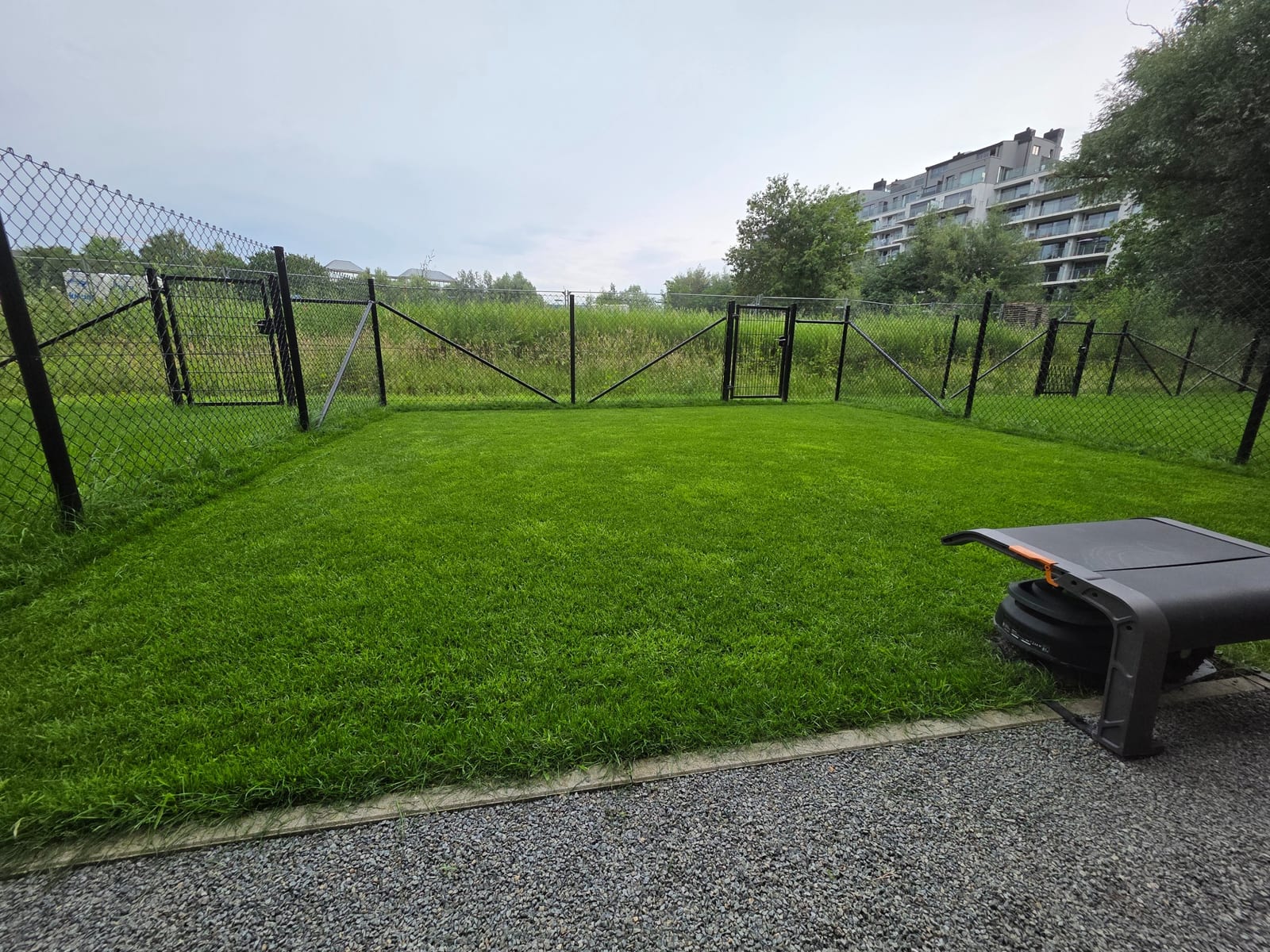
I currently water the lawn manually. Parts of it receive different amounts of sun and shade, so I want to compare moisture and soil temperature in three locations rather than rely on a single reading.
The concept connects three buried moisture probes and dedicated PT100 temperature sensing to one ESP32-S3 controller and a web dashboard. The first irrigation experiment would use one valve and sprinkler. Three measurement zones do not mean three independently watered zones.
Track the more exposed area.
Compare an intermediate location.
Track the shaded area.
Locations, burial depth, hardware and watering thresholds remain to be confirmed through selection, calibration and testing. The installation must also fit around the robotic mower.
THE QUESTION BEHIND THE PROJECT
What happens beneath the grass?
I want to understand how the same small lawn behaves differently in sun and shade. The most useful result would be a record of the soil over time, with watering decisions that can be traced back to measurements.
- Compare how quickly each location dries after watering.
- Follow soil temperature changes during the day and across seasons.
- Observe how long a moisture change takes to reach each probe.
- Identify which location loses moisture first.
- Explore seasonal and year-long comparisons once enough data has been collected.
- Measure water use if a flow meter is added later.
The proposed direction is local operation, modular hardware and software I can adapt. An open-source release is an option to consider once the prototype and documentation exist.
02 / PROPOSED HARDWARE
The pieces of the system.
Manufacturer photographs below are reference examples of component types, not equipment I have assembled or tested. Final models and compatibility are still under consideration.
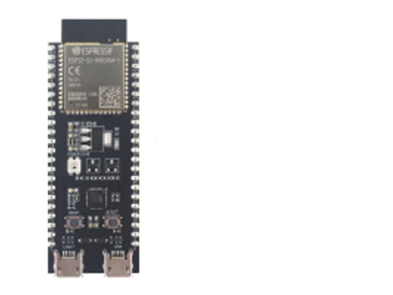
ESP32-S3 controller
The planned central controller: read sensors, communicate over Wi-Fi and coordinate irrigation.
Photo & reference: Espressif ESP32-S3-DevKitC-1 ↗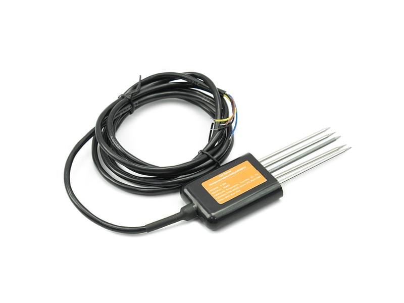
Soil sensors × 3
Combined moisture and temperature probes for comparing sunny, intermediate and shaded parts of the lawn.
Photo & reference: DFRobot SEN0604 — RS485 sensor example ↗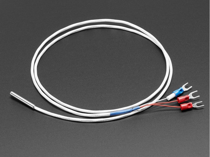
PT100 soil temperature sensor
A dedicated platinum RTD probe for soil temperature, separate from moisture measurement. A reader such as MAX31865 would connect it to the ESP32-S3 over SPI; probe sealing, burial suitability and calibration remain to be checked.
Photo & reference: Adafruit three-wire PT100 — probe example ↗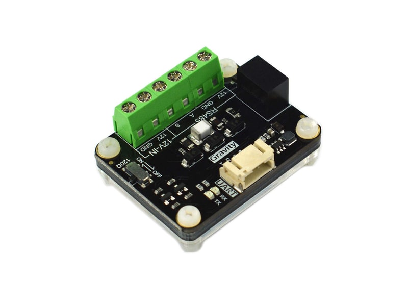
RS485 interface
A proposed link between the sensor bus and the controller. Sensor protocol and electrical compatibility will be checked before selection.
Photo & reference: DFRobot DFR0845 — interface example ↗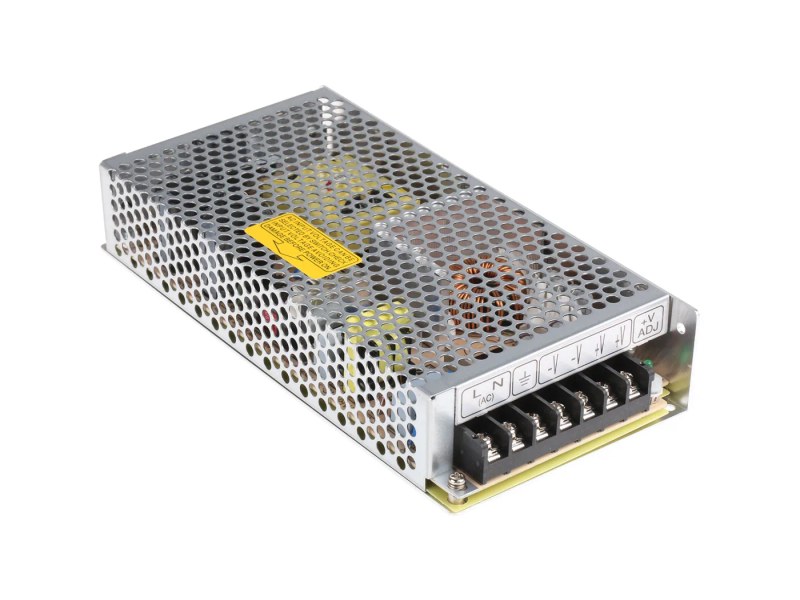
Mean Well industrial power supply
A planned 12 V industrial Mean Well supply inside the enclosure, with regulated power for the controller. A 12 V model in an enclosed metal housing is intended; the final power rating will follow the load calculation.
Photo & reference: Mean Well RS series — enclosed industrial supply example ↗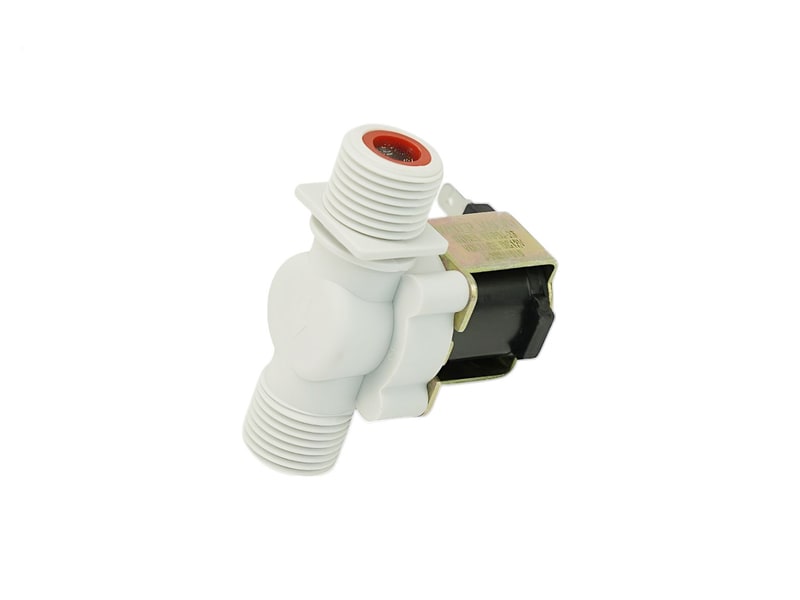
Irrigation valve
One normally closed 12 V DC valve is planned for the first test, using the existing tap, hose and a sprinkler.
Photo & reference: DFRobot FIT0498 — valve example ↗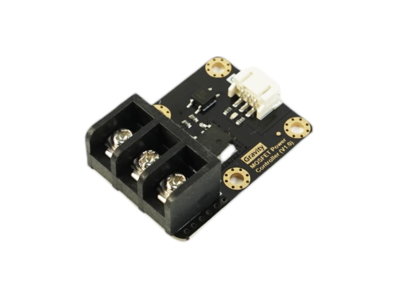
Valve driver
A MOSFET driver and inductive-load protection would let the controller switch the valve without powering it directly.
Photo & reference: DFRobot DFR0457 — driver example ↗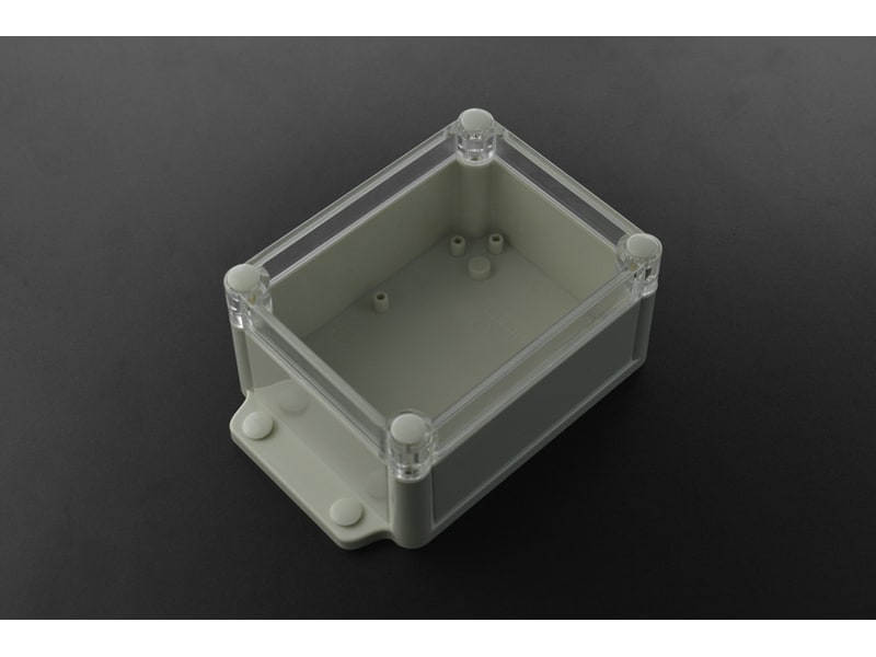
Outdoor enclosure
A protected enclosure would house the controller and connections, with suitable cable entries and access for maintenance.
Photo & reference: DFRobot FIT0724 — enclosure example ↗03 / SYSTEM CONCEPT
One controller. Two paths.
↓ Shared sensor bus → RS485 interface → ESP32-S3
↓ Separate temperature input over SPI
↓ Wi-Fi
Web dashboardReadings · History · Zone comparison
↓ Control signal
Driver → Valve → SprinklerOne watering circuit in the first prototype
Power concept: industrial Mean Well 12 V supply for compatible loads, with regulated power for the controller.
04 / DASHBOARD STUDY
See the differences over time.
A planned web interface would show moisture, soil temperature, measurement freshness and comparisons between the three zones. Historical trends would help evaluate watering and recovery.
Soil moisture
Three zones. One view of the lawn.
24.8%
More exposed34.5%
Intermediate area43.2%
More shelteredC++ firmware, Wi-Fi, RS485 and a React dashboard are proposed directions. The final software stack has not been selected.
05 / PLANNED NEXT STEPS
A prototype in stages.
- Select and test one probe. Confirm communication, repeatable readings and calibration in the actual soil.
- Build the first dashboard. Display readings and their age, then record trends and add the other monitoring zones.
- Test one valve manually. Check control, shut-off behaviour and a maximum watering duration before enabling automatic operation.
- Evaluate automation. Validate sensor fault handling and watering rules; consider weather data, a flow meter and additional valves later.
This is a future project, with no completed controller, field trials or release yet. My next step is choosing a small first prototype that I can test and learn from.